- 您现在的位置:买卖IC网 > Sheet目录135 > MBR3100 (ON Semiconductor)DIODE SCHOTTKY 3A 100V DO-201AD
�  �
�
� � �  �
�
� �  �
�
� � �  �
�
� � � MBR3100�
� � http://onsemi.com�
� � 2�
� � THERMAL CHARACTERISTICS�
� � Characteristic�
� � Symbol�
� � Max�
� � Unit�
� � Thermal Resistance, Junction?to?Ambient (see Note 3, Mounting Method 3)�
� � RJA�
� � 28�
� � °C/W�
� � ELECTRICAL CHARACTERISTICS�
� � (T�
� � L�
� � = 25�
� � °C unless otherwise noted)�
� � Characteristic�
� � Symbol�
� � Max�
� � Unit�
� � Maximum Instantaneous Forward Voltage (Note 2)�
� � (iF�
� � = 3.0 Amps, T�
� � L�
� � = 25�
� � °C)�
� � (iF�
� � = 3.0 Amps, T�
� � L�
� � = 100�
� � °C)�
� � vF�
� � 0.79�
� � 0.69�
� � V�
� � Maximum Instantaneous Reverse Current @ Rated dc Voltage (Note 2)�
� � TL�
� � = 25�
� � °C�
� � TL�
� � = 100�
� � °C�
� � iR�
� � 0.6�
� � 20�
� � mA�
� � 2. Pulse Test: Pulse Width = 300 s, Duty Cycle = 2.0%.�
� � IF(AV), AVERAGE FORWARD CURRENT (AMPS)�
� � 0 2.01.0 3.0 4.0 5.0�
� � 0.5�
� � 1�
� � 1.5�
� � 2�
� � 2.5�
� � P , AVERAGE POWER DISSIPATION (WATTS)�
� � F (AV)�
� � TA, AMBIENT TEMPERATURE (°C)�
� � 20 10040 8060�
� � 4�
� � 2�
� � 0�
� � dc�
� � 120 140 160 180�
� � I , AVERAGE FORWARD CURRENT (AMPS)�
� � F (AV)�
� � VR�
� � REVERSE VOLTAGE (VOLTS)�
� � 0.0001�
� � 02010 30 40�
� � 0.001�
� � 0.002�
� � 0.005�
� � 0.01�
� � 0.05�
� � 0.02�
� � 0.1�
� � 0.5�
� � 0.2�
� � 1�
� � vF,�
� � INSTANTANEOUS VOLTAGE (VOLTS)�
� � 0.1 0.3 0.4 0.50.2�
� � 0.6 0.8 0.9�
� � 5�
� � 0.2�
� � 0.1�
� � 3�
� � 2�
� � 1�
� � 0.7�
� � 0.3�
� � 0.05�
� � 0.5�
� � I , REVERSE CURRENT (mA)�
� � R�
� � i , INSTANTANEOUS FORWARD CURRENT (AMPS)�
� � F�
� � 25°C�
� � 100°C�
� � TJ= 150°C�
� � 50�
� � 30�
� � 20�
� � 10�
� � 1 1.2 1.31.1�
� � 50 60 80 90 10070�
� � 0.0002�
� � 0.0005�
� � 25°C�
� � 100°C�
� � TJ�
� � = 150�
� � °C�
� � 125°C�
� � 1�
� � 3�
� � 5�
� � 6�
� � 7�
� � 8�
� � 3�
� � 3.5�
� � 4�
� � dc�
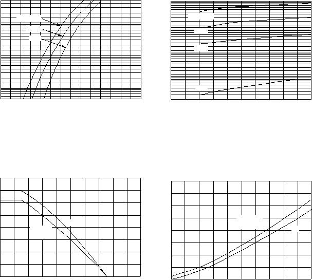
� � *The curves shown are typical for the highest voltage device in the�
� � voltage grouping. Typical reverse current for lower voltage selections�
� � can be estimated from these curves if VR�
� � is sufficient below rated V�
� � R.�
� � SQUARE�
� � WAVE�
� � SQUARE�
� � WAVE�
� � Figure 1. Typical Forward Voltage�
� � Figure 2. Typical Reverse Current*�
� � Figure 3. Current Derating�
� � (Mounting Method #3 per Note 3)�
� � Figure 4. Power Dissipation�
� 发布紧急采购,3分钟左右您将得到回复。
相关PDF资料
MBR340RLG
DIODE SCHOTTKY 3A 40V DO-201AD
MBR360RLG
DIODE SCHOTTKY 60V 3A DO201AD
MBR40250G
DIODE SCHOTTKY 40A 250V TO-220AC
MBR5H100MFST1G
DIODE SCHOTTKY 100V 5A SO-8FL
MBR735
DIODE SCHOTTKY 7.5A 35V TO-220AC
MBR745
DIODE SCHOTTKY 45V 7.5A TO220AC
MBR760
DIODE SCHOTTKY 7.5A 60V TO220-2
MBRA210LT3G
DIODE SCHOTTKY 10V 2A SMA
相关代理商/技术参数
MBR3100_06
制造商:ONSEMI 制造商全称:ON Semiconductor 功能描述:Axial Lead Rectifier
MBR3100G
功能描述:肖特基二极管与整流器 3A 100V RoHS:否 制造商:Skyworks Solutions, Inc. 产品:Schottky Diodes 峰值反向电压:2 V 正向连续电流:50 mA 最大浪涌电流: 配置:Crossover Quad 恢复时间: 正向电压下降:370 mV 最大反向漏泄电流: 最大功率耗散:75 mW 工作温度范围:- 65 C to + 150 C 安装风格:SMD/SMT 封装 / 箱体:SOT-143 封装:Reel
MBR3100G
制造商:ON Semiconductor 功能描述:Schottky Rectifier
MBR3100RL
功能描述:肖特基二极管与整流器 3A 100V RoHS:否 制造商:Skyworks Solutions, Inc. 产品:Schottky Diodes 峰值反向电压:2 V 正向连续电流:50 mA 最大浪涌电流: 配置:Crossover Quad 恢复时间: 正向电压下降:370 mV 最大反向漏泄电流: 最大功率耗散:75 mW 工作温度范围:- 65 C to + 150 C 安装风格:SMD/SMT 封装 / 箱体:SOT-143 封装:Reel
MBR3100RLG
功能描述:肖特基二极管与整流器 3A 100V RoHS:否 制造商:Skyworks Solutions, Inc. 产品:Schottky Diodes 峰值反向电压:2 V 正向连续电流:50 mA 最大浪涌电流: 配置:Crossover Quad 恢复时间: 正向电压下降:370 mV 最大反向漏泄电流: 最大功率耗散:75 mW 工作温度范围:- 65 C to + 150 C 安装风格:SMD/SMT 封装 / 箱体:SOT-143 封装:Reel
MBR3150
制造商:PANJIT 制造商全称:Pan Jit International Inc. 功能描述:SCHOTTKY BARRIER RECTIFIERS
MBR320
制造商:MOTOROLA 制造商全称:Motorola, Inc 功能描述:SCHOTTKY BARRIER RECTIFIERS 3.0 AMPERES 20, 30, 40, 50, 60 VOLTS
MBR3200
制造商:CTC 制造商全称:Compact Technology Corp. 功能描述:SCHOTTKY BARRIER RECTIFIERS